
TR-606: circuit tracing, revision differences and shared metallic voices
A separate 606 investigation covering its Schmitt bank, filters, drum inventory and unresolved component revisions.
Technical research · edition 2 · reviewed 2026-10-24
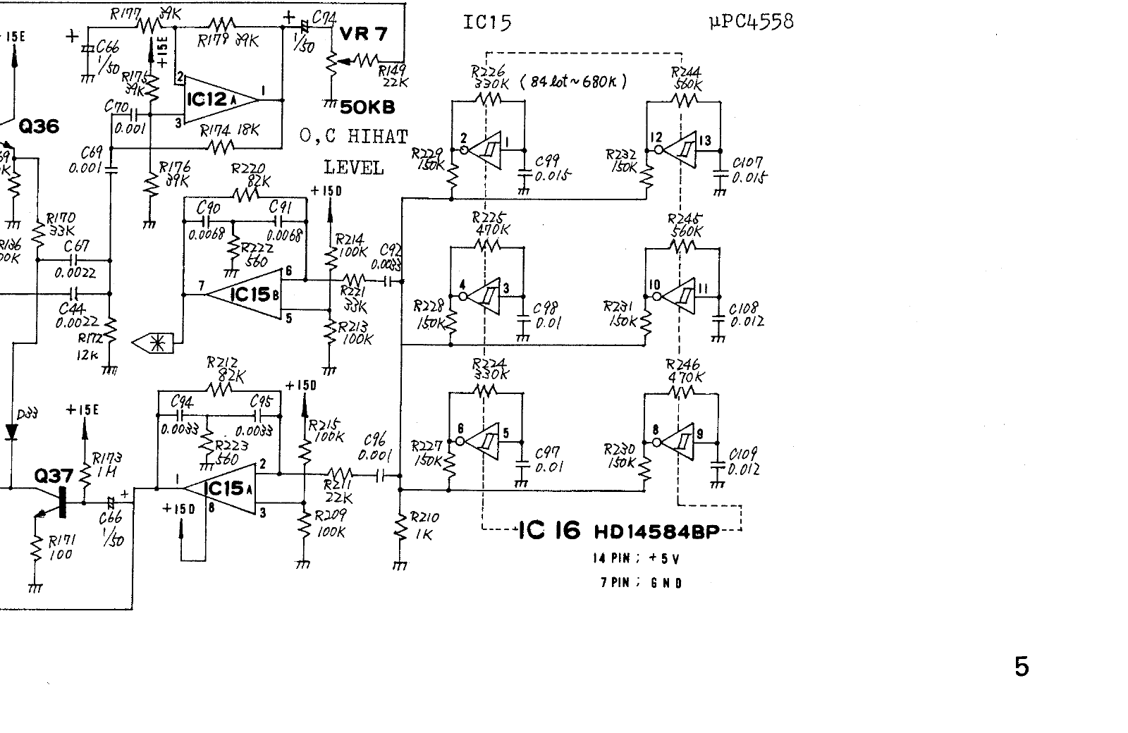
Roland TR-606 service schematic, sheet 5: six Schmitt-inverter source circuits. Image source. View full-size image
What we found
Our 606 investigation replaced a machine-wide pitch multiplier with component-specific targets. Its metallic oscillators, snare and two toms have different RC networks, and a marked manufacturing-lot resistor change materially alters one oscillator. The most useful insight is that shared topology does not justify shared coefficients or a universal “606 scale.”
We traced the service schematic and derived isolated modal and filter targets. They provide independently checkable building blocks, while leaving trigger coupling, nonlinear gates and real-unit calibration explicit.
The kick has two component-derived modes
The two bridged-T feedback networks share their trigger drive and feed the output through different resistors. The inspected scan gives:
| Stage | Capacitors | Bridge resistor | Ground resistor | Output resistor |
|---|---|---|---|---|
| IC5A | C19/C20: 56 nF each | R59: 680 kohm | R58: 3.3 kohm | R64: 10 kohm |
| IC5B | C23/C24: 15 nF each | R61: 560 kohm | R66: 12 kohm | R60: 18 kohm |
For an ideal equal-capacitor network, our engineering derivation uses
omega0 = 1 / (C sqrt(Rbridge Rground)),
alpha = 1 / (Rbridge C), and
fd = sqrt(omega0^2 - alpha^2) / (2 pi).
The resulting damped frequencies are about 59.85 and 128.04 Hz; lower T60
is 263.05 ms, with the upper decay rate 4.5333 times faster.
The impulse-coefficient and output-resistor ratio gives an upper mix of 0.57037.
Implementation uses these poles in the existing modal engine. It does not solve the complete circuit: a shaped finite trigger has a different modal excitation from the ideal impulse used for these ratios. Tune and Decay scale the reference; Body controls the upper resonance and Damping adds upper decay. Sweep, Punch, Click, Harmonics, Drive and room remain explicit synthesis extensions. The Drumatix preset disables those extensions. Acid knock remains a designed variation. The fixed sine-phase excitation and retrigger crossfade are still approximations.
Evidence: research/drums/HARDWARE_ACCURACY.md.
The oscillator bank and the revision-dependent frequency
IC16 is labelled HD14584BP, with pin 14 at +5 V and pin 7 at ground. Each oscillator is an RC Schmitt inverter, rather than a sine mode. Its output is summed through a 150 kohm resistor. Reference order below follows the schematic, not a fabricated list of 606 factory tuning values.
| Timing components | Input/output pins | R | C | RC | Summing resistor |
|---|---|---|---|---|---|
| R224/C97 | 5/6 | 330 kohm | 10 nF | 3.30 ms | R227, 150 kohm |
| R225/C98 | 3/4 | 470 kohm | 10 nF | 4.70 ms | R228, 150 kohm |
| R226/C99, earlier value | 1/2 | 330 kohm | 15 nF | 4.95 ms | R229, 150 kohm |
| R226/C99, annotated change | 1/2 | 680 kohm | 15 nF | 10.20 ms | same |
| R244/C107 | 13/12 | 560 kohm | 15 nF | 8.40 ms | R232, 150 kohm |
| R245/C108 | 11/10 | 560 kohm | 12 nF | 6.72 ms | R231, 150 kohm |
| R246/C109 | 9/8 | 470 kohm | 12 nF | 5.64 ms | R230, 150 kohm |
The R226 annotation reads 84 Lot ~ 680K. Treat that as a manufacturing-lot
change. It is not evidence that every unit built in a particular calendar year
has the later resistor. Both values must remain traceable during calibration.
The summing node has R210 = 1 kohm to ground. Ignoring loading by the following
filters and inverter output resistance, each oscillator's contribution is
(1/150k)/(1/1k + 6/150k) = 1/156 of its voltage. That gain is an engineering
derivation for the isolated passive mixer, not a fitted audio normalization.
Let L = ln((Vhigh-Vlower)/(Vhigh-Vupper)) + ln((Vupper-Vlow)/(Vlower-Vlow)). Each ideal oscillator has f = 1/(R*C*L).
Duty also depends on the switching thresholds. Thus the schematic's R/C values
alone do not fix an absolute frequency. Nominal chip thresholds, output loading,
component spread and the unit revision are consequential.
For scale only, the table below applies Vlow=0, Vhigh=5, Vlower=2.1,
Vupper=2.7 V, giving duty 47.9805%. Those are published MC14584B typical
values, not measured HD14584BP values from an original 606. Their use is an
explicit proxy assumption; they must not be advertised as calibrated 606
frequencies. ON Semiconductor/Motorola datasheet, electrical characteristics,
original table on mirror.
| RC pair | Conditional frequency |
|---|---|
| R224/C97 | 627.241 Hz |
| R225/C98 | 440.403 Hz |
| R226/C99, 330 kohm | 418.161 Hz |
| R226/C99, 680 kohm | 202.931 Hz |
| R244/C107 | 246.416 Hz |
| R245/C108 | 308.020 Hz |
| R246/C109 | 367.003 Hz |
The relative 1/(RC) structure and revision choice are firmer evidence than
an arbitrary machine-wide pitch scale. Prefer a measured chip/source sweep when
available. No original 606 oscillator capture is currently in the reference bank.
Evidence: research/drums/606-CIRCUIT-NOTES.md.
Bias resistors change the high-pass result
Useful isolated small-signal targets can be derived from the following component sets. Here the DC supply is AC ground, so two bias resistors to the rails appear in parallel. Ignoring the upper bias resistor would produce the wrong Q and frequency, and can even suggest an unstable high-pass stage incorrectly.
| Stage | Capacitors | Feedback R1 | Bias resistors / effective R2 | Ideal gain K |
|---|---|---|---|---|
| Snare Q32 | C52/C58, 1.8 nF each | R153, 22 kohm | R155/R152, 100 kohm each / 50 kohm | 1 |
| Cymbal Q40 | C59/C60, 2.2 nF each | R159, 22 kohm | R194/R195, 100 kohm each / 50 kohm | 1 |
| Hats IC12A | C69/C70, 1 nF each | R174, 18 kohm | R175/R176, 39 kohm each / 19.5 kohm | 2 |
| Cymbal IC12B | C63/C73, 1 nF each | R203, 18 kohm | R207/R208, 39 kohm each / 19.5 kohm | 2 |
The gain-two op-amp stages use equal 39 kohm feedback/bottom resistors (R179/R177 or R205/R206). Assuming ideal buffers, their nodal equations yield:
The isolated targets are Q32 f0=2665.946 Hz, Q=0.75378, Q40
2181.228 Hz, Q=0.75378, and IC12A/B 8495.062 Hz, Q=1.13545.
These are natural frequencies, not necessarily the spectral peak of the whole
voice. Source impedance, coupling capacitors, finite transistor gain, gate
impedance, summing and output loads alter the full transfer. Do not simply
cascade these isolated filters and claim a complete circuit simulation.
Evidence: research/drums/606-CIRCUIT-NOTES.md.
Snare and tom endpoints are conditional calculations
The resonators include transistor-dependent branches; their effective resistance changes with circuit state. The following is a component ledger and two ideal limiting calculations, not a calibrated pitch sweep or static replacement model.
| Voice | Bridge R | Equal resonator C | Ground branch with transistor off | Ground branch with ideal short |
|---|---|---|---|---|
| Snare IC10A | R112 820 kohm | C32/C33 27 nF | R107 330 + R115 680 = 1010 ohm | 330 ohm |
| Low tom IC9A | R324/R325, 1 Mohm each in series | C304/C305 27 nF | R323 180 + R318 820 = 1000 ohm | 180 ohm |
| High tom IC9B | R335/R336, 1 Mohm each in series | C310/C311 18 nF | R334 100 + R333 820 = 920 ohm | 100 ohm |
For the isolated equal-capacitor bridged-T, use
omega0=1/(C*sqrt(Rbridge*Rground)), alpha=1/(Rbridge*C),
fd=sqrt(omega0^2-alpha^2)/(2*pi) and T60=ln(1000)/alpha.
| Voice | Conditional fd, branch off / shorted | Ideal isolated T60 |
|---|---|---|
| Snare | 204.702 / 358.266 Hz | 152.938 ms |
| Low tom | 131.775 / 310.660 Hz | 373.019 ms |
| High tom | 206.081 / 625.204 Hz | 248.679 ms |
Do not treat these endpoint calculations as measured initial/final hit pitches. Q17/Q307/Q308 conduct continuously, not as binary ideal switches. Trigger drive, capacitor history, transistor bias and the other feedback/coupling paths must be solved before assigning an envelope trajectory. The lower/higher tom distinction already depends on different capacitance and resistance; multiplying one generic tom by an equal-tempered interval loses that structure.
The tom sub-board also contains Q305/Q306 and Q309/Q310 noise/control paths, shared rail decoupling and coupling networks. Their nonlinear interactions have not been solved here. The snare's Q30 and Q32 branches likewise require routing and envelope calibration beyond isolated pole tests. A clocked PRNG can supply a provisional noise input, but it is not the physical transistor noise source.
Evidence: research/drums/606-CIRCUIT-NOTES.md.
Applying the findings
Use the component ratios to define a neutral reference, then expose creative controls as changes relative to it. For an ideal equal-capacitor bridged-T, compute omega0, damping and T60 from the actual resistor/capacitor values rather than tuning an unrelated sine bank by ear.
When reducing a biased transistor filter for small-signal analysis, treat both supply rails as AC ground. The upper and lower bias resistors then appear in parallel. Omitting one changes Q and may even make a stable physical stage appear unstable in the derived equation. Keep revision choices alongside the coefficients so another developer can reproduce the same nominal target.
Limits and open questions
The calculated off/shorted transistor endpoints are not measured initial/final pitches. Actual conduction varies continuously and depends on trigger history. RC products in the hat envelope are time constants, not complete T60 values. The original 606 has low/high toms; a middle tom and additional tuning controls are software features. Same-unit recordings are still needed to fit the complete voices.
Primary references
Research provenance
The methods and results above are drawn from these retained research records. Dates and product versions inside the article identify the scope of each experiment; publication review does not mean the hardware or numerical tests were rerun.
research/drums/HARDWARE_ACCURACY.md— SHA-2569d5798d139a784814d46829caefa6c7c8c23234a8ca25780c806b53826b420b1research/drums/606-CIRCUIT-NOTES.md— SHA-256bd736bdc5f1886c1d0d3d26e1c96ef0fc01abacb97113e5c366c14f5a28c4d45
Related projects
KickGenerator · SnareGenerator · HiHatGenerator · TomGenerator · CymbalGenerator