TR-808 snare: coupled body, wire and Tone network
Following interactions between the resonant body, noise gate, loaded Tone mixer and output feedback.
Technical research · edition 2 · reviewed 2026-10-24
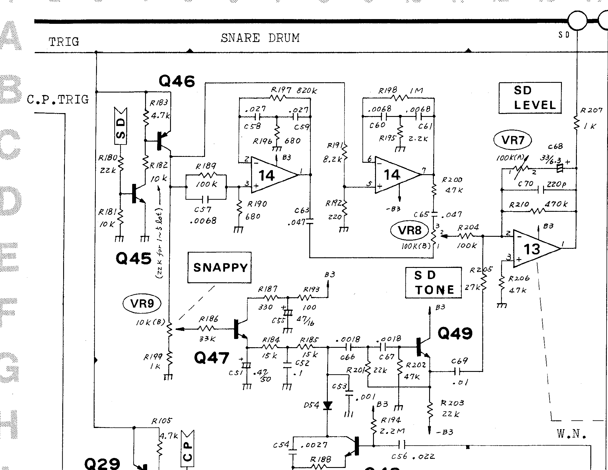
Roland TR-808 service notes: snare body and noise-path detail. Image source. View full-size image
What we found
The snare investigation found three interactions that a “two tones plus noise” design misses. The resonators have finite amplifier dynamics; the noise gate loads the envelope ladder; and the Tone/Level output network feeds current back into the wire path. At output limiting, even the summing node is no longer an ideal virtual ground.
Our most useful result is a reduction that keeps those connections while avoiding a much larger nonlinear solve. It expresses the output network as a current port of the wire system, checked against an independent unreduced network. This technique applies to many coupled analog effects.
Finite amplifier dynamics belong inside the resonator
Use the annotated later body components in the Roland service drawing, as
recorded in the body/drive/Tone/Level derivation (808-VOICE-CIRCUIT-NOTES.md#snare-driven-resonators-loaded-tone-mix-separate-wire-branch, retained research).
The lower branch is 820 kohm / 680 ohm / 56 nF / 27 nF, and the upper branch is
1 Mohm / 2.2 kohm / 6.8 nF / 15 nF. These values belong to a documented revision.
The NEC uPC4558 datasheet, G10518EJAV0DS00 (March 2004), printed p.3, specifies typical large-signal gain 100,000 and slew rate 1 V/us at +/-15 V supplies. Typical output swing is +/-14 V with a load of at least 10 kohm, and +/-13 V with at least 2 kohm. Minimum swings are lower. The current Renesas product page lists 3.5 MHz bandwidth. These are nominal part data, not measurements of the part inside an early TR-808.
The authored reference uses gain 100,000, a single dominant pole with 3.5 MHz gain-bandwidth product, symmetric 1 V/us slew and fixed +/-14 V output rails. It omits input bias/offset, common-mode overdrive, load-dependent output impedance and swing, higher poles, current limiting, temperature, saturation recovery and part variation. The output directly drives the feedback network as an ideal voltage source subject to those limits. This is not a manufacturer macro-model or a calibrated transistor-level uPC4558 simulation.
Let x be the inverting input, m the capacitor midpoint, y the output and
u the non-inverting input. Store p=x-m, q=m-y and y. Kirchhoff's laws give:
Both capacitor equations use trapezoidal integration; the stiff amplifier uses
backward Euler. The two capacitor equations make p and q affine functions
of the new output. Substitution into the amplifier equation gives a scalar
linear solve. Its positive denominator allows the simultaneous slew/rail
constraints to be imposed by clamping that solution to the intersection of
[yOld-h*slew,yOld+h*slew] and the rail interval. Capacitor voltages are then
computed using that constrained output. Clipping an independently evolved
ideal resonator would violate this feedback relationship.
tools/snare_wire_cpp/body_model.h has no heap storage, iteration, product
identity or hardcoded hardware component values. It remains a research component
while the amplifier and loading assumptions are resolved. Configuration and
invalid-input failures preserve its state. No old synthesis engine is retained.
Evidence: research/drums/808-SNARE-BODY-NOTES.md.
Snappy does not crossfade away the body
Primary source: Roland's June 15, 1981
TR-808 Service Notes,
printed pp.4, 8 and 9, with the snare drawing inspected at full resolution.
The body/Tone/Level derivation (808-VOICE-CIRCUIT-NOTES.md#snare-driven-resonators-loaded-tone-mix-separate-wire-branch, retained research)
records the revised resonator capacitors and independent body branch.
Q47 charges a capacitor ladder. D54 couples its last node to Q48's collector; Q48's base receives the shared white-noise bus through C56. Q49's high-pass input comes from the last ladder node, above D54. Its current loads that node. Q48's collector alone is not the input of an isolated high-pass cascade.
| Section | Components/connections transcribed from p.9 |
|---|---|
| Snappy | VR9 10 kΩ B; bottom through R199 1 kΩ to ground; wiper through R186 33 kΩ to Q47 base |
| Q47 supply | +B3 → R193 100 Ω → C55 47 µF to ground → R187 330 Ω → collector |
| Envelope | Emitter/C51 470 nF; R184 15 kΩ; C52 100 nF; R185 15 kΩ; C53 1 nF |
| D54 | Anode C53 node; cathode Q48 collector |
| Q48 | Collector C54 2.7 nF to ground; emitter R188 100 Ω to ground; base R194 2.2 MΩ to +B3 and C56 22 nF to WN |
| Q49 filter | C66/C67 1.8 nF; R201 22 kΩ midpoint-to-emitter; R202 47 kΩ base-to-ground |
| Q49 output | Collector +B3; emitter R203 22 kΩ to −B3; C69 10 nF/R205 27 kΩ to summing virtual ground |
The p.8 general note identifies unmarked NPNs as 2SC945(P), diodes as 1S2473. The p.4 common trigger is approximately 1 ms, 4–14 V; only cowbell/cymbal/hats use 7–14 V. WN adjustment on p.8 is 130 mV RMS.
The reference assumes an ideal post-selection trigger source; it does not model
Q45/Q46 source impedance or finite edges. From the drawing, the electrical
Snappy fraction s measured from the bottom of VR9 gives this derived source:
The 1 kΩ resistor means minimum Snappy does not imply zero drive. A software
zero-wire mute would be an extra policy. Snappy must not reduce the independent
body via body*(1-snappy). The feedback Level acts on both currents at the sum.
Evidence: research/drums/808-SNARE-WIRE-NOTES.md.
The wire path is a loaded state system
tools/snare_wire_reference.py stamps 13 node voltages: filtered Q47 supply;
Q47 collector/base; three envelope nodes; Q48 collector/base/emitter; high-pass
midpoint; Q49 base/emitter; and C69/R205 junction. It retains all nine external
capacitor voltages, including supply and noise coupling. Retriggering changes
the source without resetting those stored voltages.
Let G, C be resistor/capacitor nodal matrices, i(v) static semiconductor
terminal currents, d(t) resistor source terms, and Bc the noise-capacitor
incidence vector. Our conditional network obeys:
The second equation shows the required filter loading. Backward Euler (BE), trapezoidal and BDF2 solve the same network; BDF2 starts with one BE step. They do not implement different voice architectures. The offline Newton solver uses an analytic Jacobian, bounded iteration/line-search counts, junction-aware trial steps, and final current/voltage residual checks. Failure raises an error with a retained log rather than silently substituting another circuit.
A C1 linear continuation above exp(40) limits distant Newton trial points.
All accepted test solutions have exponents below 30: their reported equations
use the raw exponential. The independent audit verifies that condition.
This Python/NumPy reference allocates and is not realtime DSP. A realtime C++ reduction needs fixed storage, allocation tests, worst-case work and failure policies, and independent comparison with these node results. An offline KCL pass alone does not establish safe callback behavior.
Evidence: research/drums/808-SNARE-WIRE-NOTES.md.
Reduce the output to a coupled current port
output_model.h stores the two Tone coupling voltages, the shunt feedback
voltage Y-X, the series feedback-capacitor voltage, and amplifier output Y.
Here X is the summing input and W the wire node immediately before R205.
Tone and feedback capacitors use trapezoidal companions, retaining endpoint
currents as well as voltages, with exact resistor endpoints.
At Level resistance zero, both feedback-capacitor voltages satisfy the same
constraint while accounting for their old charges. After charge redistribution,
their total endpoint current is retained and divided in proportion to capacitance
so both have the same voltage derivative. This removes the unobservable
alternating circulation of ideal companions after that topology change. It does
not reset total charge or introduce an output smoothing control. This is not an exact audio
mute: the supplied zero-level probes peak around 2.2 mV.
For each next interval the passive mixer reduces to Ib - Gb*X entering the
summing input. Feedback current leaving that input is Gf*(X-Y) + If, with If
containing the capacitor companion histories. Let Gw=1/27000 and D=Gf+Gb+Gw:
Thus the output adds one nonlinear port/branch to the same 13-node wire solve, rather than a large set of extra Newton unknowns. Its current and analytic derivative enter the existing shared junction network. The current is continuous at amplifier limits; the derivative follows the accepted limiting region. The accepted summing voltage drives R205's current and therefore the wire's physical C69/Q49 feedback. Clipping an isolated final output would miss this.
CoupledWire<Termination> owns the common wire topology and semiconductor law.
The isolated wire harness uses a grounded termination to test that subcircuit;
SnareVoice always instantiates the coupled Tone/Level termination. This is a
reference boundary choice, not a selectable historical synthesis engine.
Wire and output capacitors use trapezoidal integration. Body and output
amplifiers retain their documented backward-Euler dominant-pole integration.
The body clock uses ceil(6144000/internalRate) substeps, at least one, and
rejects a configuration needing more than 256. The R189/C57/R190 shelf uses an
exact held-trigger RC update on that fine clock. Both body resonators run at
the fine rate; their final endpoint voltages feed the outer wire/output step.
This resolves the short input shelf and slew event without running the expensive
wire solve at the body clock. It is a research rate choice, not a final product
oversampling policy. The shared physical
terminal current is solved at the new endpoint. Trapezoidal wire history retains
the previous endpoint's current, including its previous summing voltage.
Tone/Snappy/Level changes preserve all physical states. The two changed linear
loads are updated from prepared baselines; junction-array copies have been
removed from nonlinear evaluation. Invalid control values are rejected before
the unchanged-value fast path. Body states commit only after the wire/output
solve succeeds.
Evidence: research/drums/808-SNARE-COUPLED-NOTES.md.
Independent numerical evidence
The output-only reference solves five simultaneous current/voltage equations,
including an independently selected amplifier limiting constraint. Fifteen
cases at 44.1/192/768 kHz cover both knob endpoints, middle values, automation
and deliberate overload. Maximum voltage error was below 5.92e-12 V, terminal
current error below 1.57e-16 A, and derivative error below 1.36e-20 A/V.
All control/processing allocation checks passed.
The complete reference independently solves physical body-node equations on the fine clock and the shelf's exact held-source response. It joins wire/output as an unreduced 18-unknown nonlinear system. It reuses the previously audited semiconductor laws but never the C++ output reduction. A second audit writes semiconductor currents, physical capacitor charges, output KCL/KVL and amplifier constraints directly from the returned states. Current and voltage errors are reported with separate units.
Ten cases at 384/768 kHz cover zero/middle/full controls, all three controls
automated at a 48 kHz cadence, and an explicit eight-times-noise overload.
Each lasts 12 ms with 1 ms, 14 V trigger pulses at 0 and 6 ms. Maximum voltage
difference was 3.311e-7 V; minimum output agreement was 176.62 dB. Worst C++
wire KCL residual was 1.660e-10 A. All processing allocations were zero.
These are numerical agreement measurements, not hardware accuracy scores.
The full-level 768 kHz case reaches the assumed output rails for eight internal
samples, with summing-input magnitude reaching 0.38745 V. This demonstrates
why the virtual-ground approximation must be revisited during amplifier limiting.
Short-probe CPU measurements remain close to one core for the 768 kHz automated
case; they include diagnostic-state copies and are not a DAW deadline guarantee.
Evidence: research/drums/808-SNARE-COUPLED-NOTES.md.
Applying the findings
For another circuit, reduce its linear part to a port relationship such as I(V) and pass both that current and its derivative into the nonlinear solve. Verify the reduction against the unreduced nodal equations, particularly when an amplifier enters slew or rail limiting. A clipper after an independently evolved signal cannot reproduce the feedback current during that event.
Test control endpoints as topology changes. At zero Level, retained capacitor charge can still discharge through the output. An exact software mute is an additional policy, not evidence that the physical state should be cleared. Preserve all branch state on retrigger and commit dependent body states only after the coupled solve succeeds.
Limits and open questions
The transistor parameters, avalanche sensitivity, amplifier rails and bandwidth are conditional model choices. The separate wire study found an unmodeled reverse-BE region under strong drive; its assumed breakdown curves are not measured 2SC945 parameters. Very small equation errors and the reported 176.62 dB numerical agreement do not quantify hardware accuracy. Research clocks and later prepared trajectories require their own production-rate checks.
Research illustrations
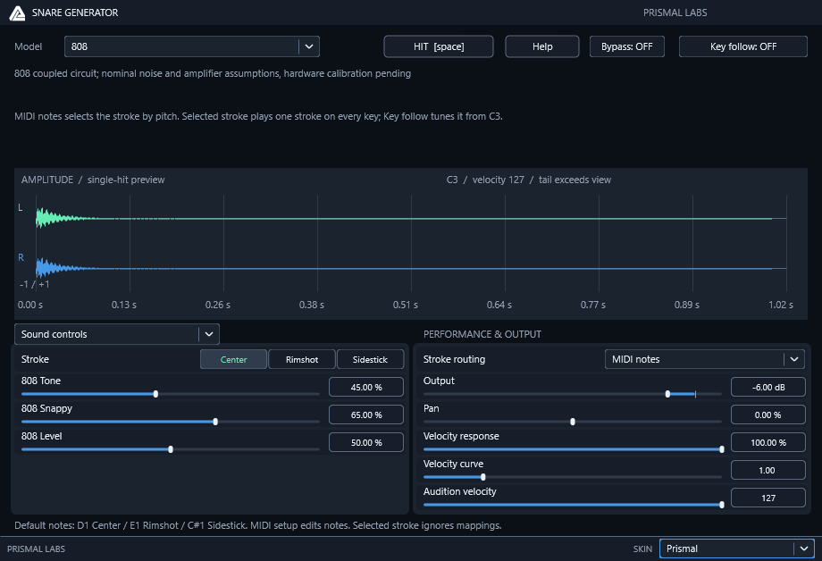
Prismal Labs native editor capture, illustrating the corresponding software project. View full-size image
Primary references
Research provenance
The methods and results above are drawn from these retained research records. Dates and product versions inside the article identify the scope of each experiment; publication review does not mean the hardware or numerical tests were rerun.
research/drums/808-SNARE-BODY-NOTES.md— SHA-2569de0c0f4ff5e32ce3dc20008e827b19f63cdeb34a4327f71b3595db6bddfec2dresearch/drums/808-SNARE-WIRE-NOTES.md— SHA-25633ac21072f25afa0eedba8ff00a366a55014cf5d2d48bb0753421b8863cc566eresearch/drums/808-SNARE-COUPLED-NOTES.md— SHA-256a6e8c1dcb8de9f0a7f47debf1fbbfe52df010d02e7d4a634bfe81c8ef3e5f545