
TR-808 cowbell: oscillators, loaded envelopes and nonlinear gates
A physically informed cowbell reconstruction with an explicitly qualified low-voltage gate model.
Technical research · edition 2 · reviewed 2026-10-24
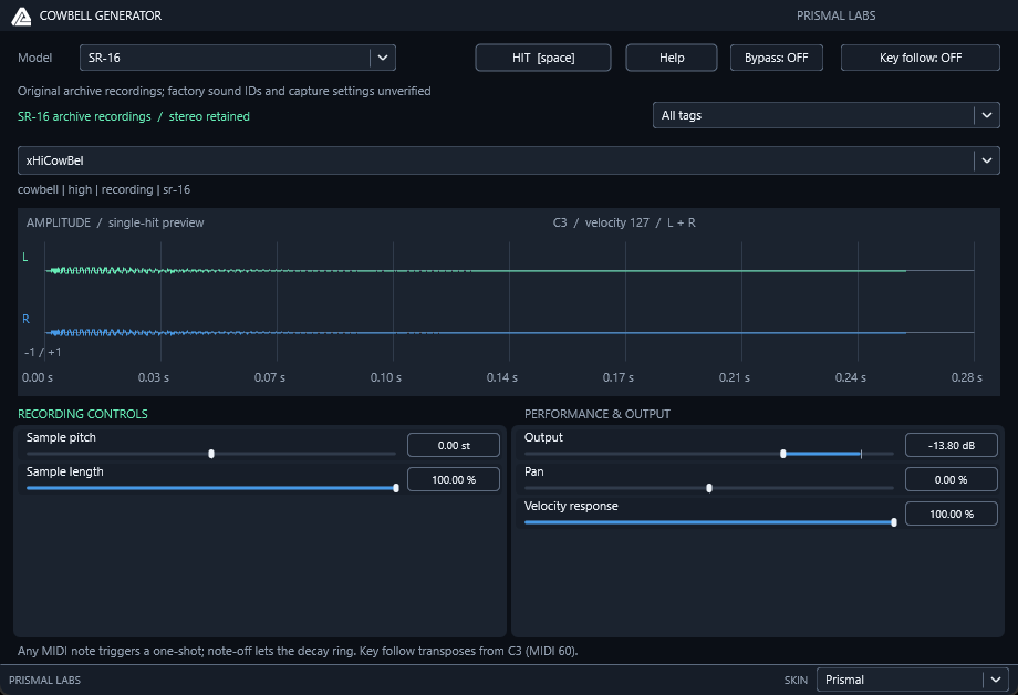
Prismal Labs native editor capture, illustrating the corresponding software project. View full-size image
What we found
The cowbell research found two errors worth checking before copying published equations: the trigger-current sign in the expanded envelope equation and a repeated gate term in its second load. We also found that the published static gate fit becomes invalid near zero and that an interior potentiometer transfer needs an independently defined wiper convention.
The practical outcome is a coupled envelope/filter model with explicit low-voltage behavior, physical capacitor state under automation, and a prepared evaluator with a quantified approximation error. These findings are reusable in other nonlinear gates and analog-model optimizations.
The component boundary
| Section | Components in the paper's Figure 1 |
|---|---|
| Envelope charge | R122 1 kohm; D2 |
| Envelope storage | C9 0.47 uF; R82 33 kohm in series with C34 1 uF |
| Envelope-to-gate loads | R28/R29 100 kohm each |
| Gate bias | R62/R64 33 kohm, R63/R65 2.2 kohm, R30/R32 470 kohm, C32/C33 10 uF, R31/R33 100 ohm; +15 V bias supply |
| Filter | R24 2.2 kohm, R25 470 kohm, R26/R27 10 kohm; C28 10 nF, C29 3.3 nF, C30/C31 2.2 nF |
| Output | C75 1 uF, R116 8.2 kohm, VR5 5 kohm, C76 22 nF, R117 22 kohm |
The source targets are 540/800 Hz and raw-inverter high-state duty 0.479805
under the paper's typical threshold assumptions. Internal tuning and component
spread remain relevant. The already tested RectangularSourceBank supplies
mathematics; it does not supply the gate/envelope/filter topology below.
Evidence: research/drums/808-VOICE-CIRCUIT-NOTES.md.
Correct the envelope current signs
Let x be C9 voltage, z C34 voltage, u1,u2 the gate collector outputs, and
T the trigger voltage. The published behavioral trigger uses a 1 ms pulse
with accent approximately 7-14 V. MIDI velocity-to-accent mapping is product
policy; it is not established by that voltage range.
Derived, with a piecewise constant-drop diode assumption Vd=0.6 V:
This form follows currents leaving each capacitor node and covers charge,
release and retrigger without resetting either stored voltage. A Shockley diode
can replace Id only after selecting its parameters and a bounded solver.
The fixed-drop model is an approximation, not an exact silicon law.
The printed attack equation (10) has -T + Vd, inconsistent with the current
direction in its own equations (6)-(7). The contribution must be +T - Vd
when expanded as above. Equation (12) repeats gate 1 in its second load term;
that term must use gate 2. These were checked visually in the PDF.
An independent diagnostic can ground both gate outputs and turn the diode off. The resulting linear state matrix in inverse seconds is:
Its poles are -127.19266459 and -10.13808977 per second. Those are an
isolated diagnostic, not the sounding gate-coupled envelope. In this case
d(0.5*C9*x^2 + 0.5*C34*z^2)/dt must equal
-(x-z)^2/R82 - x^2/R28 - x^2/R29. This energy identity catches current-sign
mistakes independently of an implementation's update equations.
Evidence: research/drums/808-VOICE-CIRCUIT-NOTES.md.
Do not extrapolate a fitted gate through zero
The primary paper fits collector low/high bounds against envelope voltage. Using its table as numerical data:
These are empirical SPICE-fit bounds, not coefficients derived from R/C values. The fit models bi-level oscillator drive. It does not establish behavior for arbitrary noise input or for the whole zero-to-14-V envelope domain.
Our evaluation exposes a required boundary check: at x=0.1 V, the fit
gives L=0.0789993 and U=0.06988 V, reversing their ordering. At x=0.01 V
both are negative. At exactly zero the negative powers are undefined. Clamping
or blending this away without a reference would be an authored tail correction.
The paper also repeats “lower edge” for the high state in its final section-6
paragraph; that is not a usable oscillator specification.
The conditional implementation below adds a conservative continuation rather than claiming calibrated near-zero behavior. A future transistor/diode solver for the bias and collector network must declare its parameters and temperature. Neither a generic saturation voltage nor a threshold copied from another voice would establish calibrated 808 evidence.
Raw oscillator high voltage increases NPN conduction and lowers its collector
voltage. Track that inversion explicitly: if q denotes raw high state, the
ideal folded gate is u=U(x)-q*(U(x)-L(x)). Raw high-state duty and collector
high-state duty are complementary. The two feedback currents in the envelope
must use the same gate outputs that feed the audio filter.
Oversampling is necessary to assess bandwidth expansion and numerical coupling. The paper uses 8x 44.1 kHz in its illustrated comparison. Reuse of a PolyBLEP source alone does not validate nonlinear gate aliasing or resampling. Compare different internal rates before selecting a production factor.
Evidence: research/drums/808-VOICE-CIRCUIT-NOTES.md.
The two inputs share one loaded filter
This is not the topology of the existing cymbal ActiveBandpass3 component.
Let m be the capacitive midpoint and y the ideal op-amp output. The inverting
input is virtual ground. Define:
This derived complex-admittance form provides an independent reference for
expanded coefficients. Arbitrary input RCs yield fourth-order transfers. With
the equal stock input branches, one pole cancels and H1=H2; filter u1+u2
through a common cubic transfer. Do not average the signals without accounting
for the factor of two, or forget loading from the inactive input branch.
Stock ascending-power coefficients after that cancellation are:
Poles are -45167.731034 and -572.162852 +/- j5400.493671 per second. A
0.1-Hz grid gives the magnitude peak at 873.9 Hz, 10.04406 dB per input.
Nodal evaluation and the paper's expanded fourth-order coefficients agreed
within 6.2e-15 complex absolute error on 1,000 logarithmic frequencies from
1 Hz to 100 kHz. These checks concern the ideal filter, not instrument output
gain or perceived pitch.
Evidence: research/drums/808-VOICE-CIRCUIT-NOTES.md.
Preserve capacitor voltage while Level moves
The subsequently added shared/include/prismal/dsp/passive_level.h realizes
the same passive network using capacitor voltages. Let Va be the input
capacitor's right node, Vw the electrical wiper, and Vo the load output. Define
x=Vin-Va across Ci and z=Vw-Vo across Co. With
Rt=Rs+P*(1-l), Rb=P*l, and load Rl:
These follow directly from the wiper KCL and the two capacitor currents, and match the new class's matrix coefficients. Its implicit trapezoidal update uses the retained derivative at the preceding endpoint and the new endpoint's matrix/input. Reconfiguration preserves both capacitor voltages and the prior endpoint derivative. Thus automated wiper values are treated as successive endpoint values in the trapezoidal rule; an ideal discontinuous resistor step specified at the start of the interval would be a different timing convention. The network contains no modeled mechanical contact noise, nonlinear taper or buffer saturation.
At l=0 the wiper is grounded: the input capacitor discharges through Rt and
the output capacitor through Rl. Previously stored z can produce Vo=-z until
it discharges, while a fresh zero-state instance is silent. Exact immediate
product muting is a separate output policy; it does not require erasing charge.
At l=1, Rt remains the positive series resistor and the same nonsingular KCL
applies. The class rejects invalid coefficients/rates transactionally and
resets both state and derivative after nonfinite processing input/arithmetic.
The independent four-unknown nodal test covered three component sets and 8,
44.1, 48, 96 and 384 kHz while repeatedly moving the wiper through both endpoints
and intermediate values. Maximum node/state error was 1.85407e-14 V.
Fixed-wiper processed impulse DTFTs differed from independent complex impedances
by at most 4.77432e-15 in absolute complex magnitude. Invalid-input recovery,
state preservation on rejected configuration and allocation-free processing/
live reconfiguration also passed. Evidence:
build/cowbell-circuit-v3/passive-level-tests.log. The test is registered as
PrismalPassiveLevel in the root/shared CMake graph.
Evidence: research/drums/808-VOICE-CIRCUIT-NOTES.md.
Quantify the lookup approximation
We prepared 1024 cubic Hermite intervals for the static gate curves above E0 = 0.5 V, retaining the separate low-voltage continuation below that boundary. To bound the approximation, differentiate the fitted curve and compare the interpolated value and slope across every interval.
For f=A*exp(g) and g=-beta*x^p, p<0,
On each positive interval [a,b], exp(g) increases while every abs(g^(n))
decreases. Their separate endpoint bounds and the triangle inequality therefore
give a conservative bound M4 on abs(f''''), summed across the two fitted
exponential terms. A cubic Hermite interval of width h has voltage error at most
M4*h^4/384. A conservative derivative error bound is 19*M4*h^3/48:
expand the target to its third-order Taylor polynomial at a, bound its endpoint
value remainder by M4*h^4/24 and derivative remainder by M4*h^3/6, and use
max(abs(h01'))=1.5, max(abs(h11'))=1 in the Hermite basis. This bound is
deliberately looser than the measured derivative error. A floating-point rounding
allowance is added to both reported limits.
Preparation checks each entire cubic for passive bounds and calculates the
exact extrema of its quadratic derivative. maximumSlopeMagnitude() includes
those polynomial extrema, so the envelope solver's root bound covers the
prepared curve itself. lookupSlopeErrorBound() describes the interpolation
error of the unclipped lower fitted branch; the global maximum slope additionally
covers the continuation and passive clipping pieces. lookupVoltageErrorBound()
also bounds the final edge voltages because clipping is nonexpansive. The two
envelope load currents have error at most the voltage bound times the sum of
their conductances.
Production-flag tests sampled 524289 voltages across the full domain, checked all
1025 table nodes and adjacent slopes, and independently evaluated the analytic
derivative. Observed maximum voltage/slope/current errors were 1.30037e-9 V,
3.04623e-7, and 2.60074e-14 A for the two 100k loads. The conservative
reported voltage/slope bounds were 8.36921e-9 V and 9.64857e-5.
The independent coupled circuit and actual filter/output processing at 44.1,
48, 96 and 384 kHz differed from analytic evaluation by at most 3.35599e-10 V
in stored voltage and 5.86365e-10 V in output; the independent KCL residual
remained below 3.3219e-12 V.
An isolated gate benchmark measured approximately 54.1 ns per analytic evaluation
and 11.1 ns per prepared evaluation on this host. These timings are descriptive,
not a CI performance assertion or a complete plug-in CPU budget. Complete-voice
performance additionally depends on source clock scheduling, filtering and
decimation and must be measured in the consuming engine. Evidence:
build/hardware-review-v2/cowbell-gate-lookup-final.log.
Evidence: research/drums/808-VOICE-CIRCUIT-NOTES.md.
Applying the findings
First verify passive energy: with the trigger off and grounded gate outputs, the capacitor energy derivative must be nonpositive. That check catches a sign error independently of the integration code. Next test fitted curves over the entire operating domain for ordering, finite values, slope and passivity.
Our continuation joins zero carrier contrast at a fit-derived boundary, retains capacitor charge and finite dissipation, and caps the upper edge to prevent reverse envelope current in the chosen passive approximation. An earlier continuation produced an artificial long tail and was rejected. For performance, prepare the static curve off the audio path and bound interpolation error; do not declare an optimization equivalent from a few plotted points.
Limits and open questions
The conservative near-zero continuation is not a measured transistor cutoff. The lookup uses 1024 cubic Hermite intervals above the continuation region; the bounds and measurements describe that approximation. The product uses 8× processing and a 32-sample delay, while stock same-pitch retriggers preserve source/filter state. Key-follow polyphony and immediate zero-Level mute are software extensions, and hardware calibration remains open.
Primary references
Research provenance
The methods and results above are drawn from these retained research records. Dates and product versions inside the article identify the scope of each experiment; publication review does not mean the hardware or numerical tests were rerun.
research/drums/808-VOICE-CIRCUIT-NOTES.md— SHA-2569da5e278618d175cee17e438f8d02d52be10b74621642a80c0edd57e7b58cea3Drums/CowbellGenerator/README.md— SHA-2561eb6ebc5d3b1de46877f2c5e7df31dcc8078d3000fa034c4b0870c5685f4d3a9