
TB-303: accent, slide and original pattern behavior
How stored charge, note overlap and the original programming workflow shape a monophonic bass line.
Technical research · edition 2 · reviewed 2026-10-24
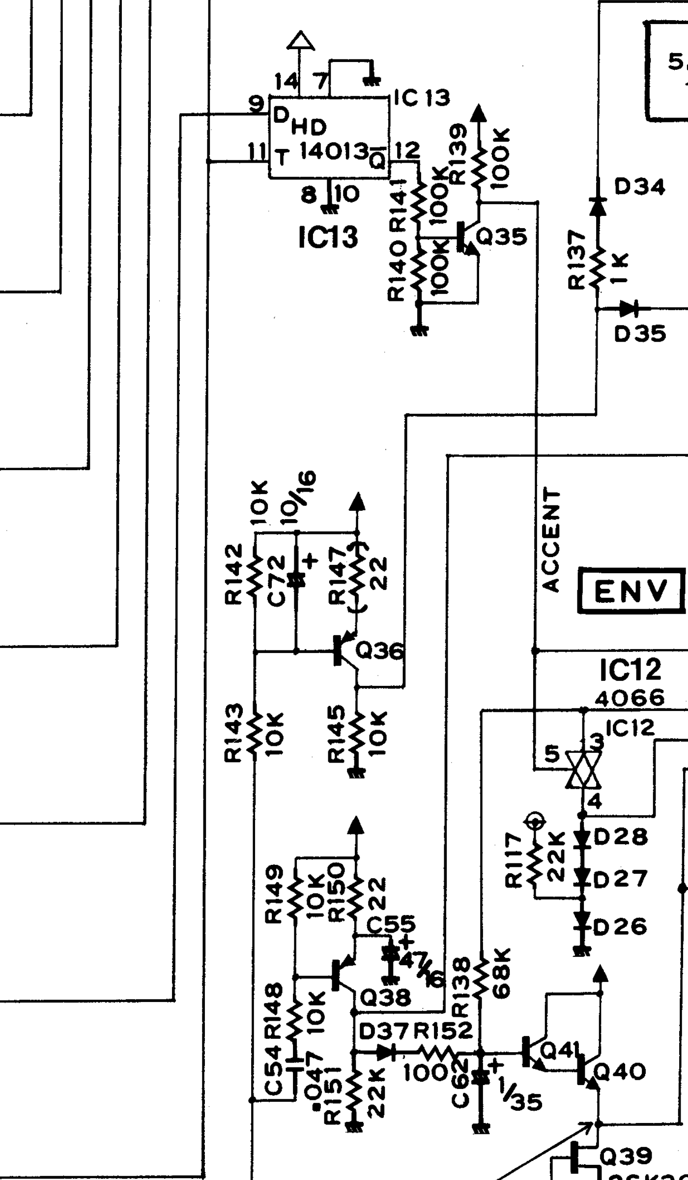
Roland TB-303 service notes: main-envelope circuit detail. Image source. View full-size image
What we found
Accent and slide are coupled control behaviors. Our reconstruction separates the main/filter envelope, the volume envelope and the C13 accent store, then connects their loads. This matters because an accented note changes a discharge path and adds stored control energy; it is not equivalent to multiplying the output of an ordinary ADSR. Overlapping notes can also change pitch while preserving gate and charge.
The most reusable finding is a state contract: a retrigger changes circuit excitation, while a slide changes pitch control. Neither operation grants permission to reset every envelope or filter state. That contract can be used in other monophonic synthesizers even when their exact circuits differ.
The main envelope and the real meaning of Decay
The trigger path contains R149 (100 kohm), R148 (10 kohm), C54 (47 nF), Q38, R150 (22 ohm), C55 (47 uF) and R151 (22 kohm). D37 and R152 (100 ohm) charge C62 (1 uF). R138 (68 kohm) and VR6 (0–1 Mohm) connect C62 to D28/D27/D26; R117 (22 kohm) biases the bottom diode from 5.333 V. The accent-controlled 4066 section bypasses VR6. Q41/Q40 buffer C62; Q39 has gate/source grounded.
The decay value is the electrical VR6 resistance fraction, not a resolved
logarithmic knob law. The switch has an explicit nominal on resistance of
300 ohm and is open when inactive. The service notes show 300 ohm typical
at 10-V supply; using it at the modeled rail is an approximation, not a
characterized 12-V switch model.
Whittle's hardware notes distinguish the original main and volume envelopes and identify the fixed short main-envelope decay on accented notes. The present implementation changes the actual VR6 discharge path and retains capacitor voltage when the accent input changes. It does not reset C62 on a retrigger or hold it constant during a gate.
Eleven coordinates are Rail, Base38, Edge, Collector38, DiodeCathode, Store, Middle, Output, Return, DiodeMid and BiasDiode. Three physical capacitor-current histories accompany C55, C54 and C62. They use trapezoidal integration, including the change in C54's externally driven gate terminal.
Startup explicitly charges C55 to 12 V and leaves C54/C62 at zero voltage. The other nodes are solved with those capacitor constraints, and initial capacitor currents are reconstructed from KCL. This is not a fully settled leakage equilibrium. Attempting that equilibrium exposed poor conditioning around the nearly floating decay diodes; it is not required for this declared startup. Reset restores both prepared voltages and initial current histories.
Processing uses the shared Newton solver with a uniform physical-current merit function because the Darlington nodes have no passive conductance for a resistor-only row scale. A charging-edge initial guess preserves capacitor history. If needed, at most 32 source-continuation roots use the same timestep and histories; only the final root advances state. Each root has at most 64 Newton iterations and 24 line-search trials. The 2-pA KCL and 20-nV update gates remain unchanged. Failure keeps the preceding physical state. Processing uses fixed storage and performs no heap allocation.
Evidence: research/tb303/MAIN-ENVELOPE.md.
Accent has its own store and a shared load
The original Roland service notes,
1982-02-19, PDF page 5, show the connections below. The page-8 parts list specifies
VR4 as two 50-kohm linear sections and VR7 as a 50-kohm linear pot. The local PDF
renders accent-pot-wiring-inspect.png and accent-wire-run-inspect.png resolve
wire crossings and the VR7-wiper junction at D24. They are ignored reference
material, not product assets.
| Node | Connection |
|---|---|
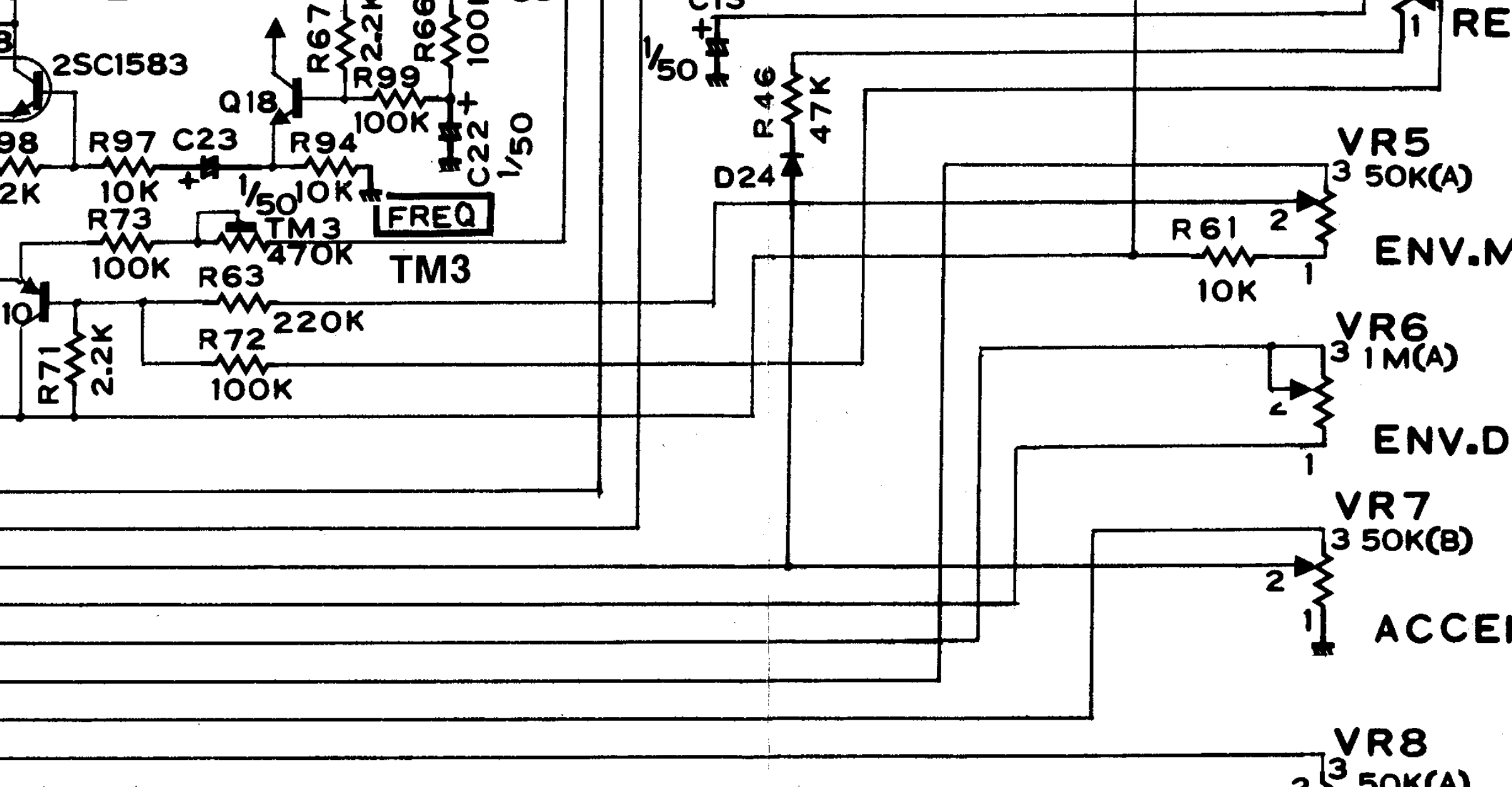
| Input | IC12 pin 2 and VR7 terminal 3; the closed switch joins pin 1 at Q40/Q39 output |
| Wiper | VR7 terminal 2, D24 anode and a separate VCA accent-load port |
| DiodeCathode | D24 cathode and bottom of R46, 47 kohm |
| ResLow | Top of R46 and terminal 1 of VR4's second section |
| Store | Terminal 3 of that VR4 section and C13, 1 uF to ground |
| Output | VR4 second-section wiper, through R72 (100 kohm) to Q10 base |
VR7 terminal 1 is grounded. At maximum Resonance the second wiper approaches C13; at minimum it approaches R46. The first VR4 section continues to control audio feedback with the same electrical travel. These are two real resistive sections, not a separate envelope coefficient. R72 can charge C13 from the filter's bias network even while D24 blocks the Accent input. An empty C13 is therefore a startup condition, not its settled no-note voltage.
Robin Whittle's 2019 manual, pages 4–5, independently describes the original resonance-dependent sweep and charge retained in C13 between accents. The original schematic determines this implementation's exact wiring; Devil Fish additions are not silently substituted for original components.
The analog switch uses the existing model's declared 300-ohm on resistance and an ideal open state. Each pot segment retains a 1-ohm contact resistance. D24 uses the declared nominal silicon law, Is=10 fA and VT=25.85 mV; no measured diode fit, junction charge, switch leakage or charge injection is claimed. These assumptions need sensitivity checks. Accent selection controls this switch and the existing decay bypass together; the actual digital latch/timing remains processor work.
AccentSweep has six node voltages and one physical C13 current history.
Its standalone ports are main-envelope voltage, Q10-base voltage, electrical
Accent/Resonance fractions, switch state and current drawn by the VCA accent branch.
Preparation fixes C13 to zero volts and solves the remaining algebraic nodes.
Initial capacitor current is reconstructed from KCL. Processing uses trapezoidal
charge integration; the passive diode-off solution seeds Newton, with a forward
diode estimate when needed. Final roots retain 2-pA KCL and 20-nV correction gates.
No guessed voltage is committed before convergence. Rejection and reset preserve
both capacitor voltage and current.
OscillatorFilterNetwork<true,true,true> appends these nodes at coordinates
70–75. The first 70 coordinates retain their established ordering. C13 is the
22nd trapezoidal capacitor; oscillator junction charge retains backward Euler.
The IC12 branch has equal/opposite current at main-envelope Output (61) and
Accent Input (70). R72 has equal/opposite current at Q10 base (50) and Accent
Output (75). Each endpoint conductance is stamped once. No ideal accent-voltage
source remains in this specialization.
The combined AccentControls accepts Cutoff, Env Mod, TM3, Decay, gate, Accent,
accented-decay/switch state and the still-conditional Q36 and Accent-wiper load currents.
The existing resonance argument controls both VR4 sections. Startup matches the
envelope's combined VR5/IC12 load to below 1e-14 A, the accent-output interface to
below 1e-10 V, and the existing tail interface to below 1e-10 V, with bounded
iterations. All startup capacitors retain their explicitly documented conditions.
The prepared symbolic graph includes the IC12 connection even if it starts open. Switching does not rebuild the graph or allocate. All 76 voltages, 22 physical capacitor histories, compensated updates and gate predictor history participate in the same accepted interval and rollback policy. The existing bounded Newton, source continuation and adaptive reset handling remain unchanged.
Evidence: research/tb303/ACCENT-SWEEP.md.
Volume and accent meet at the VCA
The Roland service notes,
1982-02-19, PDF page 5, supply these connections. Local renders
volume-control-inspect.png, volume-trigger-wire-inspect.png,
vca-input-inspect.png, vca-accent-return-inspect.png and
vca-accent-junction-inspect.png resolve the long wires. R119's distant connection
is now traced to VR7's wiper. D36 is separately fed by Q38 collector.
| Node | Connection |
|---|---|
| Volume (0) | Q36 collector; R137 (1 kohm) and D35 anode |
| Trigger (1) | Q38 collector; D36 anode |
| Gate (2) | Digital Gate; D34 cathode |
| Accent (3) | VR7 wiper; R119 (47 kohm) |
| Vca (4) | BA662 pin 1; Q31 collector and accent-injection diode cathode |
| Clamp (5) | R137 and D34 anode |
| Feed (6) | D35 cathode and R133 (2.2 kohm) |
| Emitter31 (7) | Q31 emitter; series R131 (220 kohm) and R133 to Feed |
| Base31 (8) | Q31 base; C42 (1 uF) to ground, R123 (1.5 Mohm) to +12 V, R132 (100 ohm) |
| Collector32 (9) | Q32 collector and R132 |
| Emitter32 (10) | Q32 emitter; R130 (100 ohm) to ground |
| Base32 (11) | Q32 base; C41 (0.1 uF) to ground, R134 (22 kohm) |
| TriggerCathode (12) | D36 cathode and R134 |
| AccentStore (13) | R119, C36 (0.033 uF) to ground and R120 (22 kohm) |
| AccentAnode (14) | R120 and accent-injection diode anode |
R133/R131 are an unbranched 222.2-kohm series resistance; R131 is not a shunt. The diode above IC15 is printed D27, duplicating the envelope bias diode designator elsewhere on this scan. Code names it by terminals and retains that printed ambiguity instead of silently renaming it.
The raw linear() and Law equations retain all terminal currents/Jacobians for
mapping into the full voice. Standalone processing constrains the first five
voltage rows; other rows express physical KCL. Port current is positive entering
this circuit, so negative Vca current is delivered to BA662 pin 1. R123's +12-V
source is ideal. Controls must be finite and within 0–12 V, with Gate limited to
6 V and Vca to 1.2 V. These ranges define test ports, not MIDI control ranges.
Evidence: research/tb303/VOLUME-ENVELOPE.md.
Timing findings from the playable sequencer
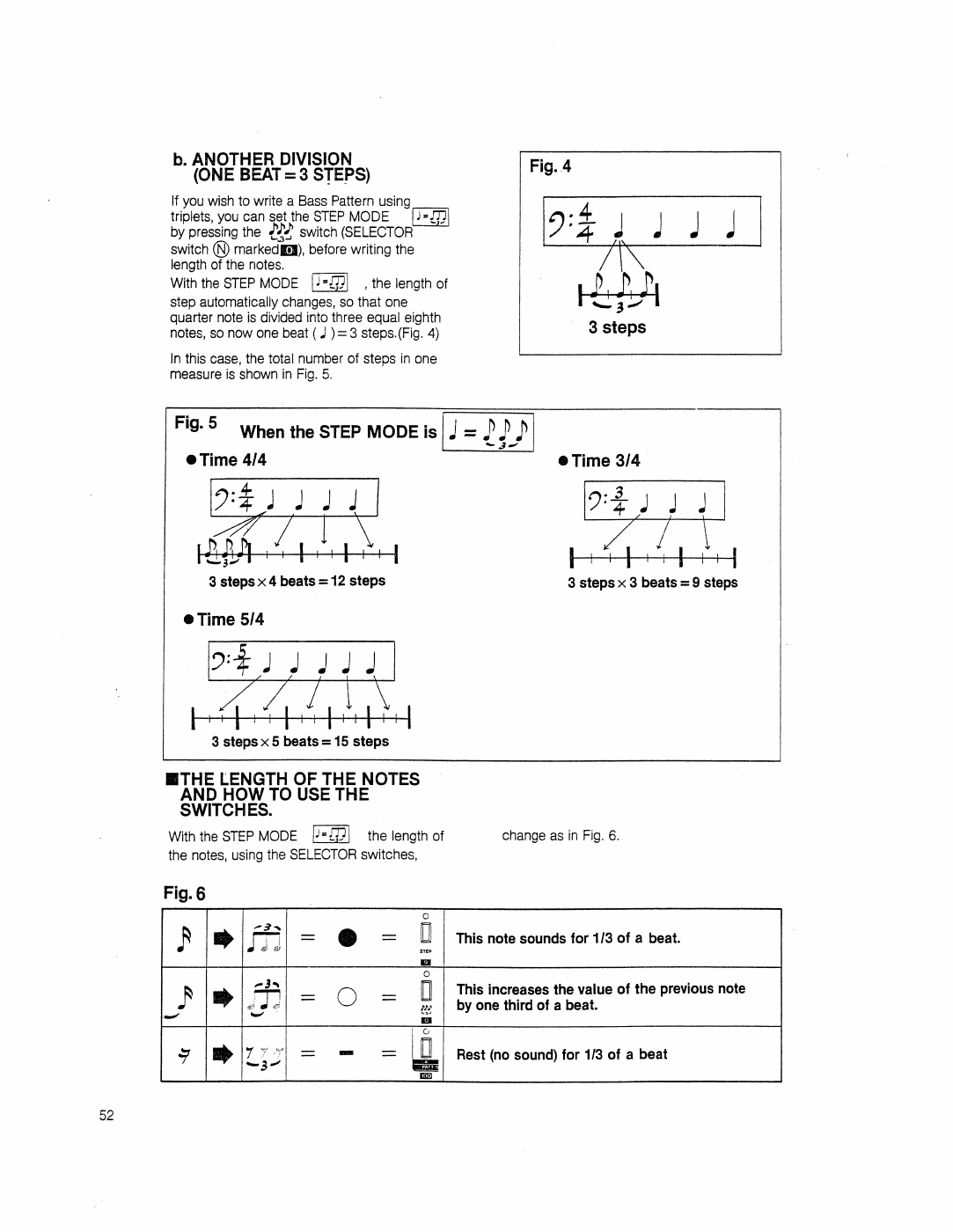
In Pattern Write, press TIME MODE, then press WRITE/NEXT (TAP) once for each stored step. The Note, Tie or Rest LED identifies that step, and the footer shows its number. Checking timing triggers no audition and does not edit or dirty the pattern. After the last step the writer automatically returns to Normal, as described on p. 16 of the original owner's manual. The final indicator remains visible while WRITE/NEXT is held, then clears on release. Press TIME MODE again to restart from step one. Stored lengths, including fifteen-step triplets, determine where review ends.
Note, Tie and Rest buttons still enter timing data in Time Mode. Pattern, mode and state changes clear the review indicator. The review position is transient; it is not written into the preset. Native frame tests check all three indicators, restart and automatic exit; message tests verify that review sends neither audition nor pattern-edit messages. Portable tests check the tape and bounds.
Evidence: PL-33/PANEL-CONTROLS.md.
Applying the findings
Test a separate note, an overlapping note, release back to an older held note, and the final note-off. Observe pitch, gate and capacitor histories independently. Then repeat with accent on the first or second note and with a changed Decay setting during the tail. An implementation that sounds plausible on isolated hits can still violate these transitions.
Use the differential equation i = C dv/dt to decide what must persist. A resistor or switch change alters the subsequent derivative; it does not normally erase the stored voltage. Preserve old and new endpoint conditions according to the integrator's declared timing convention.
Limits and open questions
Electrical potentiometer fractions are not a measured mechanical taper. The nominal 4066 resistance and transistor/avalanche laws are declared assumptions. Pattern-entry and host timing tests establish software behavior, not exact original CPU firmware timing. Component checks and an actual DAW performance pass remain different evidence.
Research illustrations
Roland TB-303 service notes: accent potentiometer and connected wiring. Image source. View full-size image
Roland TB-303 original owner's manual, printed page 52: the triplet programming example inspected during sequencing research. Image source. View full-size image
Primary references
- Roland TB-303 service notes
- Roland TB-303 original owner's manual
- Robin Whittle: Devil Fish engineering manual
Research provenance
The methods and results above are drawn from these retained research records. Dates and product versions inside the article identify the scope of each experiment; publication review does not mean the hardware or numerical tests were rerun.
research/tb303/MAIN-ENVELOPE.md— SHA-25663d0980a08bf84bf70c722c7b30d374f893b16a3824e4542eddf16b038f70eacresearch/tb303/ACCENT-SWEEP.md— SHA-256d74c94f4b4516843ec0e123271adab9ce8b228eaf653a91c38e2b41d2495f607research/tb303/VOLUME-ENVELOPE.md— SHA-256037842c39ec1cd4dd5bb75e5b8ae2c9e0fc701930580f63040006f3f140e4307PL-33/PANEL-CONTROLS.md— SHA-25678fb715f14a24591bb6642bfa96a3ca018b9bd816eae191866626a6620ef93b1